Cáp Tín Hiệu KURAMO “FDF” “FDF-SB” | Chính Hãng – Chịu Uốn – Cáp Robot
Factory Automation Cable
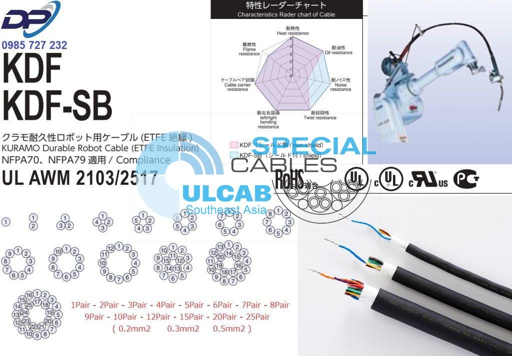
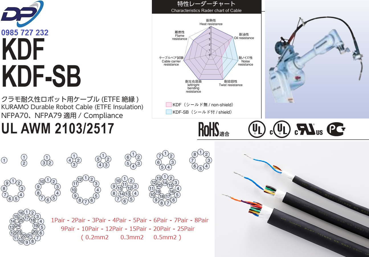
KDF
KDF-SB
クラモ耐久性ロボット用ケーブル (ETFE 絶縁 )
KURAMO Durable Robot Cable (ETFE Insulation) CE
NFPA70、NFPA79 適用 / Compliance
UL AWM 2103/2517
用 途 / Use
■ケーブルベアへの配線※
Wiring to cable carriers
■ロボットアーム旋回部分への配線※
Wiring to robot arm turning part
■耐ノイズ性要求箇所への配線(シールド付タイプ:KDF-SB)
Wiring to the portion requiring noise resistance (Shielded type : KDF-SB)
※配線方法の詳細につきましては、NFPA70 及び NFPA79 をご参照下さい。
If you would like to know the detail of how to wiring in USA, you should refer to NFPA70 and NFPA79
特 長 / Features
■ふっ素樹脂絶縁・耐屈曲性
Fluorocarbon resin insulation, bending resistance
■耐ノイズ性 (シールド付タイプ:KDF-SB)
Noise resistance(Shielded type:KDF-SB)
■耐熱性
Heat resistance
■シースつや消し
Sheath mat type
■ UL・cUL 規格ケーブル
Cable designed to UL, cUL standards
■ NFPA70, NFPA79 対応(通信用 CM)
Corresponding to NFPA70 and NFPA79
(Type CM for Communications Circuits)
■ CE 対応
Corresponding to CE
使用温度範囲 / Temperature range
■固定時 / Fixed:-40 〜 105℃ ※
■可動時 / Flexing:0 〜 105℃
※ 0℃以下でご使用の際は、衝撃・屈曲・振動等の外的力が加わらないようにしてください。
If you use it in temperature less than 0℃ , you should be careful about shocks,
flexure, vibration and so on.
曲げ半径 / Bending radius
■固定時:ケーブル外径の 4 倍以上推奨
Fixed:4 times or more of the cable diameter
■可動時:ケーブル外径の 7.5 倍以上推奨
Flexing:7.5 times or more of the cable diameter
RoHS 指令 / RoHS Directive
■適合 / Conformity
認 証 / Approvals

■テクニカルデータ / Technical data
| ケーブルタイプ Cable designation |
UL CM(UL 444) | cUL CM | UL AWM(UL 758) | cULAWM | |
| CM | STYLE 2103 | STYLE 2517 | AWM | ||
| 適用サイズ / Adaptation size | 全サイズ All Size |
1P,2P | 3P 以上 3P or more |
全サイズ All Size |
|
| 定格電圧 / Voltage rating | – | 300V | |||
| 定格温度 / Temperature rating | 105℃ | ||||
| 試験電圧 / Test voltage | AC2000V・1min | ||||
| 難燃性 / Flame resistance | Vertical-Tray Flame Test | FT2 | VW-1 | FT2:2P 以下 / 2P or less FT1:3P 以上 / 3P or more |
|
| 適用規格 / Adaptation standard | UL 444 CSA C22.2 No.214 | UL 758 | CSA C22.2 No.210 | ||
KDF,KDF-SB は電気用品安全法が適用されませんので、信号及び通信回路などの弱電流回路にご使用下さい。
KDF and KDF-SB are excluded to “Electrical Appliance and Material Safety Law”, for this reason, those cable should be used for cable connection to signal and communication circuits and other weak current elctrical circuits JAPAN.
< 1 〜 25P に適用 / Appliance to 1-25P >
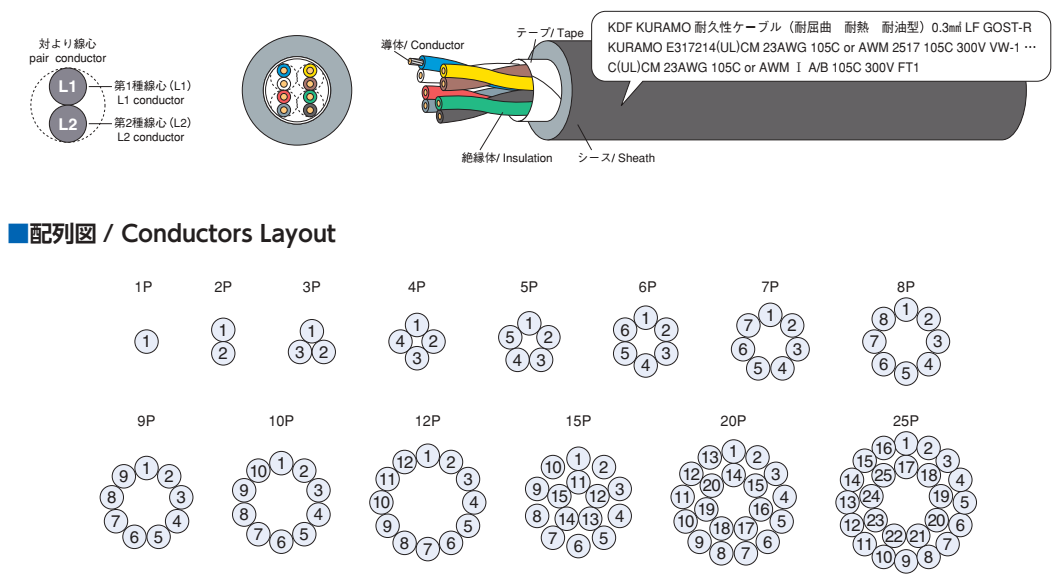
■構造概略 / Construction
| 品名 / Code | KDF | KDF-SB | ||
| 項目 / Item | 0.2㎟ | 0.3㎟ ,0.5㎟ | 0.2㎟ | 0.3㎟ ,0.5㎟ |
| 導体 / Conductor | すずめっき軟銅集合線 Strands of wire composed of tin-coated annealed copper |
すずめっき軟銅複合より線 Rope-lay stranded of tin coated annealed copper |
すずめっき軟銅集合線 Strands of wire composed of tin-coated annealed copper |
すずめっき軟銅複合より線 Rope-lay stranded of tin coated annealed copper |
| 絶縁体 / Insulation | ふっ素樹脂(ETFE)/ Fluorocarbon resin (ETFE) | |||
| 対より / Conductor stranding | 線心を対より / Twisted pair | |||
| より合わせ / Pair strand | 対より線心を円形により合わせ / Strands of twisted pair in circular form | |||
| テープ / Tape | テープ重ね巻き / Tape wrap around cores | |||
| シールド / Shield | – | すずめっき軟銅線編組 / Tin coated annealed copper braid | ||
| シース / Sheath | 耐油・耐熱性ビニル混合物(黒色)/ Oil and heat resistant PVC (black) | |||
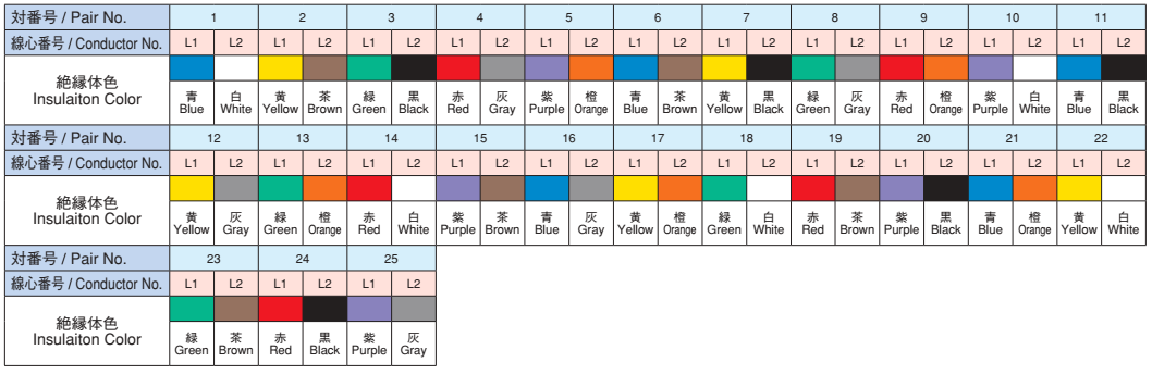
■線心識別 / Conductors identification
例示 / Example : KDF 8(4P)× 0.3㎟(23AWG)
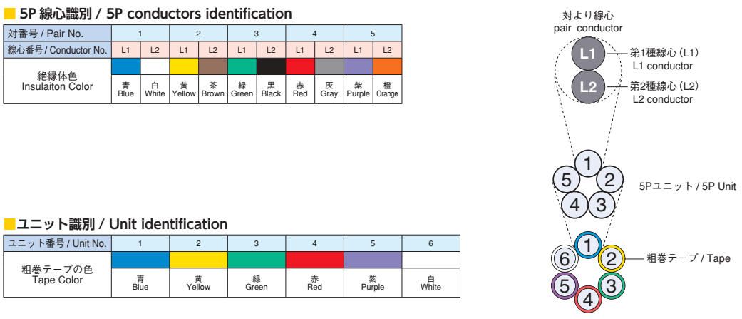
< 30P に適用 / Appliance to 30P >
■構造概略 / Construction
| 品名 / Code | KDF | KDF-SB | ||
| 項目 / Item | 0.2㎟ | 0.3㎟ ,0.5㎟ | 0.2㎟ | 0.3㎟ ,0.5㎟ |
| 導体 / Conductor | すずめっき軟銅集合線 Strands of wire composed of tin-coated annealed copper |
すずめっき軟銅複合より線 Rope-lay stranded of tin coated annealed copper |
すずめっき軟銅集合線 Strands of wire composed of tin-coated annealed copper |
すずめっき軟銅複合より線 Rope-lay stranded of tin coated annealed copper |
| 絶縁体 / Insulation | ふっ素樹脂(ETFE)/ Fluorocarbon resin (ETFE) | |||
| 対より / Conductor stranding | 線心を対より / Twisted pair | |||
| ユニット / Unit | 5P を円形にユニットより合わせ / Circular (5P) into unit | |||
| ユニットより合わせ / Unit stranding | 6 ユニットを円形により合わせ / Circular (6 units) | |||
| テープ / Tape | テープ重ね巻き / Tape wrap around cores | |||
| シールド / Shield | – | すずめっき軟銅線編組 / Tin coated annealed copper braid | ||
| シース / Sheath | 耐油・耐熱性ビニル混合物(黒色)/ Oil and heat resistant PVC (black) | |||
■線心識別及び配列図 / Conductors identification and layout
■構造表 / Construction table
| 導体 / Conductor | 絶縁 / Insulation | 心数 Number of conductors |
在庫 / Stocks | シールド無し / Non-shield | シールド付き / Shield | 電気特性 / Electrical characteristics | ||||||
| 公称断面積 Nominal cross sectional area |
外径(約㎜) Diameter (Approx.㎜) 〈Construction 構成 〉 |
外径(約㎜) Diameter (Approx.㎜) |
シールド無 Non-shield |
シールド付 Shield |
シース外径(約㎜) Sheath diameter (Approx.㎜) |
概算重量 Approx.weight (kg/ km) |
シース外径(約㎜) Sheath diameter (Approx.㎜) |
概算重量 Approx.weight (kg/ km) |
許容電流 Allowable ampacity (A) |
導体抵抗 Conductor resistance 20℃(Ω / ㎞) |
絶縁抵抗 Insulation resistance (M Ω㎞) |
|
| 0.2㎟ <25AWG> |
0.6 <40/0.08> |
1 | 1P | ○ | ○ | 3.5 | 16 | 4 | 23 | 6 | 105 以下 (Max 105) |
1500 以上 (Min 1500) |
| 2P | ○ | ○ | 5.7 | 35 | 6.2 | 50 | 5 | |||||
| 3P | ○ | ○ | 6.2 | 45 | 6.7 | 55 | 4 | |||||
| 4P | ○ | ○ | 6.4 | 50 | 6.9 | 60 | 4 | |||||
| 5P | ○ | ○ | 7.2 | 60 | 7.7 | 80 | 4 | |||||
| 6P | ○ | ○ | 7.7 | 70 | 8.2 | 90 | 4 | |||||
| 7P | ○ | ○ | 8 | 80 | 8.5 | 95 | 4 | |||||
| 8P | ○ | ○ | 8.8 | 90 | 9.3 | 115 | 3 | |||||
| 9P | 9.4 | 100 | 9.9 | 125 | 3 | |||||||
| 10P | ○ | ○ | 10 | 110 | 10.5 | 135 | 3 | |||||
| 12P | ○ | ○ | 11.5 | 135 | 12 | 165 | 3 | |||||
| 15P | ○ | ○ | 11 | 140 | 11.5 | 170 | 3 | |||||
| 20P | ○ | ○ | 12 | 185 | 12.5 | 215 | 2 | |||||
| 25P | ○ | ○ | 14 | 240 | 14.5 | 285 | 2 | |||||
| 30P | 17.5 | 330 | 18.5 | 380 | 2 | |||||||
| 0.3㎟ <23AWG> |
0.8 <3/20/0.08> |
1.3 | 1P | ○ | ○ | 4.1 | 21 | 4.6 | 29 | 8 | 71.5 以下 (Max 71.5) |
1500 以上 (Min 1500) |
| 2P | ○ | ○ | 6.8 | 50 | 7.3 | 65 | 7 | |||||
| 3P | ○ | ○ | 7.3 | 60 | 7.8 | 75 | 6 | |||||
| 4P | ○ | ○ | 8.1 | 75 | 8.4 | 90 | 5 | |||||
| 5P | ○ | ○ | 8.7 | 85 | 9.2 | 110 | 5 | |||||
| 6P | ○ | ○ | 9.5 | 100 | 10 | 125 | 5 | |||||
| 7P | ○ | ○ | 10 | 115 | 10.5 | 140 | 5 | |||||
| 8P | ○ | ○ | 11 | 130 | 11 | 155 | 4 | |||||
| 9P | 11.5 | 140 | 12 | 175 | 4 | |||||||
| 10P | ○ | ○ | 12.5 | 170 | 13 | 200 | 4 | |||||
| 12P | ○ | ○ | 14.5 | 215 | 15 | 260 | 4 | |||||
| 15P | ○ | ○ | 14 | 220 | 14.5 | 265 | 4 | |||||
| 20P | ○ | ○ | 15.5 | 285 | 16 | 330 | 3 | |||||
| 25P | 17.5 | 355 | 18 | 410 | 3 | |||||||
| 30P | 21.5 | 490 | 22.5 | 570 | 3 | |||||||
| 0.5㎟ <21AWG> |
1.1 <3/33/0.08> |
1.6 | 1P | ○ | ○ | 4.7 | 28 | 5.4 | 40 | 11 | 43.4 以下 (Max 43.4) |
1500 以上 (Min 1500) |
| 2P | ○ | ○ | 7.9 | 65 | 8.2 | 85 | 9 | |||||
| 3P | ○ | ○ | 8.9 | 85 | 9.4 | 110 | 8 | |||||
| 4P | ○ | ○ | 9.8 | 110 | 10.5 | 135 | 7 | |||||
| 5P | ○ | ○ | 11 | 130 | 11.5 | 160 | 7 | |||||
| 6P | ○ | ○ | 12 | 150 | 12.5 | 185 | 7 | |||||
| 7P | ○ | 12.5 | 175 | 13 | 210 | 7 | ||||||
| 8P | ○ | ○ | 13.5 | 200 | 14 | 240 | 6 | |||||
| 9P | 14.5 | 230 | 15 | 270 | 6 | |||||||
| 10P | ○ | ○ | 16 | 275 | 16.5 | 325 | 6 | |||||
| 12P | ○ | ○ | 17.5 | 320 | 18.5 | 375 | 6 | |||||
| 15P | ○ | ○ | 17 | 335 | 17.5 | 395 | 5 | |||||
| 20P | ○ | ○ | 19.5 | 445 | 20 | 495 | 5 | |||||
| 25P | 21.5 | 530 | 22 | 600 | 4 | |||||||
| 30P | 28 | 720 | 28.5 | 780 | 4 | |||||||
○は在庫品です。/ ○ : Stocks
■許容電流について / Allowable ampacity
・許容電流値は周囲温度 30℃、空中 1 条敷設時の計算値を示し、保証値ではありません。
Allowable ampacity (A) for cable is based on calculation under aerial one-cable and temperature at 30℃ , not repressenting a guaranteed value.
・周囲温度 30℃以上の場合は、次の電流減少係数を表の値に乗じて下さい。
Allowable ampacity cable at ambient temperature abobe 30℃ is to be determined by multiplying the current value by the appropriate current reduction factorin
the following table1.
・許容電流の値は、JCS0168 により算出した値であって、保証値ではありません。
The allowable ampacity for cable are the calculated by JCS0168, but not guaranteed.
JCS0168…日本電線工業会規格 “33kV 以下電力ケーブルの許容電流計算”
“Calculation of the current rating of power cables for rated voltage up to and including 33kV”
■表 電流減少係数 / Table1 Current reduction factors
| 周囲温度 / Ambient temperature (℃) | 30 | 35 | 40 | 45 | 50 | 55 | 60 | 65 | 70 | 75 | 80 | 85 | 90 | 95 | 100 |
| 電流減少係数 / Current reduction factors | 1.00 | 0.97 | 0.93 | 0.89 | 0.86 | 0.82 | 0.77 | 0.73 | 0.68 | 0.63 | 0.58 | 0.52 | 0.45 | 0.36 | 0.26 |